If you’re in the part assembly business, you are probably familiar with terms like torque, clamp load, and mean shift, but you may not entirely understand their meaning or how they relate to one another. This should help provide some clarity.
What is torque?
Torque is simply force x distance. This explains why our units of measure are often Foot-Pounds, Newton-Meters, & Inch-Pounds. However, it is not torque we’re after. What we really need to securely hold two or more parts together is clamp load. Unfortunately, clamp load does not allow for inexpensive and practical direct measurement. In its place, we rely on torque, which has a known relationship to clamp load, and which is a practical and relatively inexpensive means of measurement to help ensure that the parts we’re assembling are held together properly.
But there’s a catch . . .
Most of the torque we apply to a threaded fastener is lost due to friction under the bolt head and friction in the threads. In many instances, only 10% of the torque we apply is transferred to the force needed to hold the parts together. See the pie graph below (and the gray pie segment, which represents clamp load).
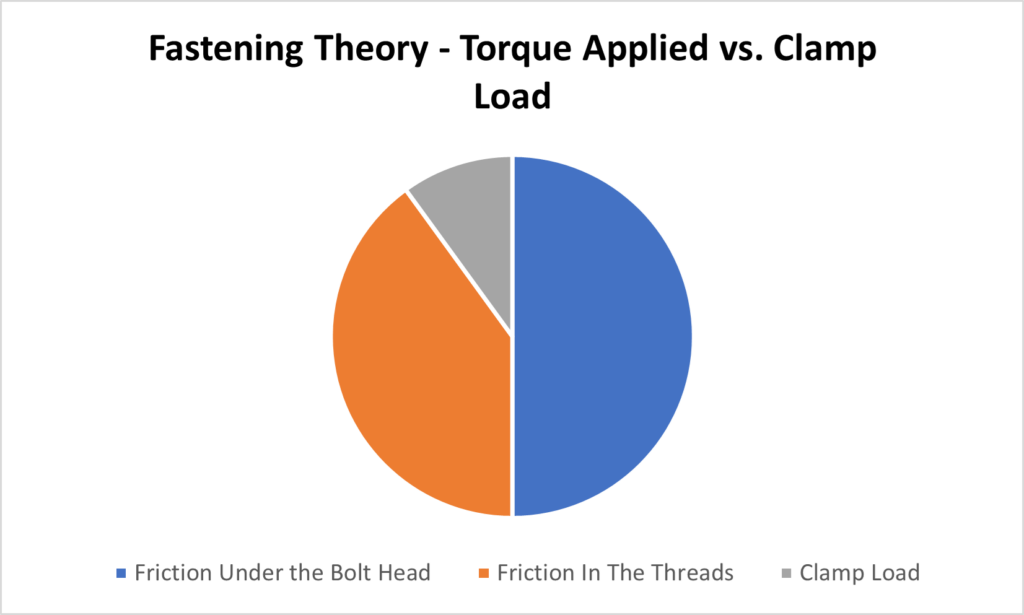
The size of these pie segments can change too. Let’s say, for instance, that new bolts are used that have a lubricant applied to the threads (with all other factors remaining unchanged). Should this happen the size of the orange pie slice will shrink, with a subsequent increase in the gray pie slice. Sounds good, right? Not always. Let’s say, for instance, that we are already applying all the force the parts can take. Applying more may damage the parts. When this happens, at the very least the damage may be visible, and quality assurance measures can intervene to have these parts set aside to avoid shipping defective parts off to your customer. However, there are more sinister scenarios that may take place. Let’s say, for example, that the parts don’t break, but in stead the bolts enter the Plastic Zone. Now you have parts that are being held together with compromised fasteners, which may break after shipment. But wait . . . what is the Plastic Zone?
There are four (4) major stages that occur when assembling parts with a threaded fastener. They are:
Phase 1 – Rundown – in a typical threaded fastener application you may see very little torque build-up during this stage. You’re simply running down the fastener, with the underside of the bolt head having yet to contact the part.
Phase 2 – Draw-Down – the underside of the bolt head has contacted the part, and torque has started to increase as the parts are being drawn together.
Phase 3 – Elastic Phase – the bolt now begins to stretch, which creates our desired clamp load. When the force is removed the bolts return or “snap back” to their original shape.
Phase 4 – Plastic – in most instances, this is something you want to avoid. When the fastener has entered the Plastic Zone it is inalterably changed. It will no longer “snap back” to its original dimensions. Your only hope if you’ve inadvertently entered this phase is for the fastener to break during the assembly process. This way at least it will be visibly apparent, and you’ll be able to have the part removed for inspection and/or disassembly. Parts with fasteners in the Plastic Zone that haven’t broken risk breaking during transport or while in your customer’s possession.
So, we’ve established that we need to create clamp load to hold our parts together, and to do so we utilize torque as our means of measurement. Does this mean that a torque program designed for one part will behave the same way on an entirely different part? Probably not. This brings us to Joint Rate, and the concept of Hard and Soft joints.
Joint Rate – angles of rotation required after having seated the fastener to achieve the target torque.
Hard Joint – think of this as a metal-on-metal application, where the torque build-up once the fastener has been seated is very quick. A good example would be a fastener that turns a mere 30⁰ after seating before achieving its target torque.
Soft Joint – this involves an application where there is a lot more compression in the parts, so much so that the fastener rotates a considerable number of degrees after being seated before reaching its target torque. A good example would be parts that include gaskets or spring washers. In these types of applications, you may see a full 180⁰ of rotation, or more, before the desired torque has been reached.
When we program DC electric torque tools, we’re able to manipulate speed to optimize our program and “hit” our desired torque with a great deal of accuracy. On a hard joint, for example, we may run the fastener down at 80% of the tool’s speed until the half-way point of our target torque, and then reduce it dramatically to crawl before reaching our final torque. Keep in mind that on a hard joint the torque build-up is going to be very quick, so we want the tool running slowly to provide the time needed to shut-off accurately.
On a soft joint the torque buildup is going to be a lot gentler, so we’ll be able to run the tool faster.
I frequently use the analogy of driving your car to a stop sign. If you race towards the stop sign at 100 miles an hour and don’t hit the break until you at the sign you’re going to careen through the intersection. To stop on the line, you’re going to want to start suppressing the brake well in advance, so the car has a chance to come to a stop at the line. This is how I frequently illustrate working with a hard joint.
The problem I see quite a bit is torque tools being set on stationary transducers with little consideration being made for the conditions of the part, or the part’s joint rate. Say for example you set the tool with a stationary transducer that is mimicking a soft joint, yet your application is metal-on-metal with a threaded fastener going into a clean threaded hole. While the tool may “hit” your desired torque on the stationary transducer, it may wildly over-torque when being applied on the part. If you’re using something that doesn’t provide feedback, you may never know that you’re exceeding your desired torque. I see this a lot with shut-off pneumatic tools.
This bring us to Mean Shift – or the different torque results when the same tool is utilized on both a hard and a soft joint.
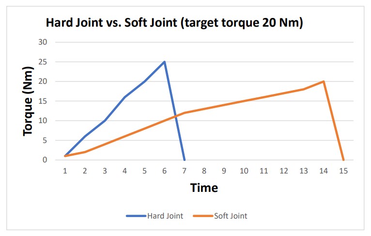
The graph above illustrates the theoretical torque results of a tool programmed for a soft joint being used on a hard joint. While the tool shut-off at precisely 20 Nm when used on the soft joint, it dramatically overshot when on the hard joint. The tool simply didn’t have the time needed while on the hard joint to shut off at the desired torque. There was simply too much inertia to contend with.
The difference between the two is commonly referred to as Mean Shift.
* This is a theoretical illustration. The graph above was not pulled from a DC electric tool. It was created purely to illustrate a point.
If you’re working with programmable DC electric torque tools, you’re going to want to create a torque program with the joint rate in mind. If you’re using the same tool on entirely different joints, you may need to toggle between two entirely different torque programs.
This is just the tip of the iceberg when it comes to fastening theory, but it should nonetheless provide a good foundation, especially for those new to the world of threaded fastener assembly.
Should you have any questions, please feel free to reach out via our contact us page.